プロローグ
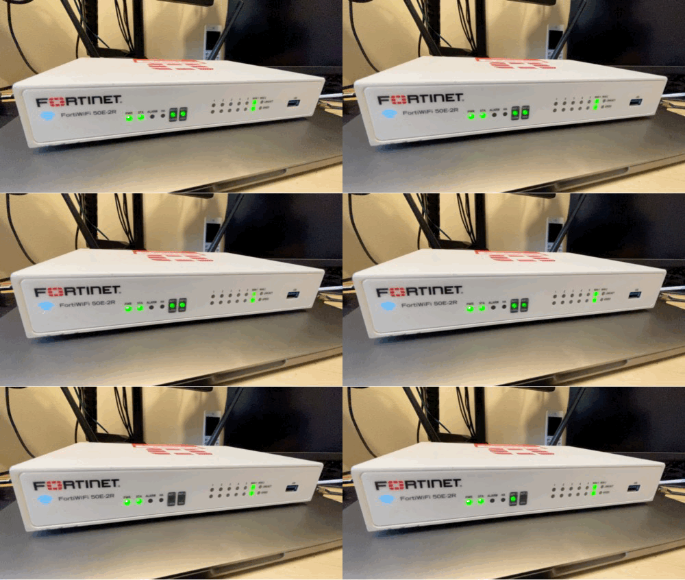
FG-50EにOpenWrtを入れて使っていましたが、USB Wi-FiドングルとZigbeeドングルをUSBハブ経由で接続していると動作が不安定なため、Wi-Fiインクルードな2Rを購入してみました。
また、FG-50系はOverlay拡張が出来るそうなので、2Rでも出来るか色々試行錯誤したので備忘録として残します。なお、参考にして実施される方は自己責任でお願いします。


initramfsイメージを実行
まず、シリアルコンソール経由で2R用のOpenWrtイメージをTFTPで書き込みます。
詳細は他様のブログを参照ください。
なお、今は2R用のイメージが提供されているので、ブートローダで弾かれることなく普通に書き込みできました。
overlay拡張イメージをビルド
次に別のUbuntu環境でoverlayを拡張したイメージをビルドします。
ほとんどは他様のサイト通りですが、2R用にカスタマイズが必要でした。

ざっくりFG-50Eと異なる部分を挙げると下記の通り。
- menuconfig では2R用のをプロフィール選択
- 有志の方が作成された50E向けに用意されているDTSファイルを2R向けに書き換え
menuconfigでは「Target Profile → Fortinet FortiGate 52E-2R → Save/Exit」のステップを踏みます。
次にDTSファイルの編集です。
ちなみに、以下がデフォルト状態の「armada-385-fortinet-fwf-50e-2r.dts」です。
// SPDX-License-Identifier: GPL-2.0-or-later OR MIT

#include "armada-385-fortinet-fg-5xe.dtsi"

/ {
	model = "Fortinet FortiWiFi 50E-2R";
	compatible = "fortinet,fwf-50e-2r", "marvell,armada385", "marvell,armada380";
};

&pciec {
	status = "okay";
};

&pcie1 {
	status = "okay";
};

&pcie2 {
	status = "okay";
};
このデフォルト内容を有志の方が作成された50E向けに用意されているDTSファイルに反映して、2R用のDTSファイルとして使います。
以下がそのまま使える改変済みのDTSファイルで、指定の保存先に「armada-385-fortinet-fwf-50e-2r.dts」として上書き保存しました。
12行目の機種名を2R用に変更、198−208行目が元のPCI関連の記載のようです。(2R用の)
// SPDX-License-Identifier: GPL-2.0-or-later OR MIT

/dts-v1/;

#include <dt-bindings/gpio/gpio.h>
#include <dt-bindings/input/input.h>
#include <dt-bindings/leds/common.h>
#include "armada-385.dtsi"

/ {
	model = "Fortinet FortiWiFi 50E-2R";
	compatible = "fortinet,fwf-50e-2r", "marvell,armada385", "marvell,armada380";

	aliases {
		led-boot = &led_status_green;
		led-failsafe = &led_status_red;
		led-running = &led_status_green;
		led-upgrade = &led_status_green;
		label-mac-device = ð0;
	};

	chosen {
		stdout-path = "serial0:9600n8";
	};

	memory@0 {
		device_type = "memory";
		reg = <0x00000000 0x80000000>; /* 2GB */
	};

	soc {
		ranges = <MBUS_ID(0xf0, 0x01) 0 0xf1000000 0x100000
			  MBUS_ID(0x01, 0x1d) 0 0xfff00000 0x100000
			  MBUS_ID(0x09, 0x19) 0 0xf1100000 0x10000
			  MBUS_ID(0x09, 0x15) 0 0xf1110000 0x10000
			  MBUS_ID(0x0c, 0x04) 0 0xf1200000 0x100000>;
	};

	gpio-keys {
		compatible = "gpio-keys";
		pinctrl-names = "default";
		pinctrl-0 = <&pmx_gpio_keys_pins>;

		reset {
			label = "reset";
			linux,code = <KEY_RESTART>;
			gpios = <&gpio1 22 GPIO_ACTIVE_LOW>;
		};
	};

	gpio_leds: gpio-leds {
		compatible = "gpio-leds";
		pinctrl-names = "default";
		pinctrl-0 = <&pmx_gpio_leds_pins>;

		led-0 {
			gpios = <&gpio0 30 GPIO_ACTIVE_LOW>;
			color = <LED_COLOR_ID_RED>;
			function = LED_FUNCTION_ALARM;
		};

		led-1 {
			gpios = <&gpio1 0 GPIO_ACTIVE_LOW>;
			color = <LED_COLOR_ID_RED>;
			function = "ha";
		};

		led_status_green: led-2 {
			gpios = <&gpio1 1 GPIO_ACTIVE_LOW>;
			color = <LED_COLOR_ID_GREEN>;
			function = LED_FUNCTION_STATUS;
		};

		led-3 {
			gpios = <&gpio1 3 GPIO_ACTIVE_LOW>;
			color = <LED_COLOR_ID_GREEN>;
			function = "ha";
		};

		led-4 {
			gpios = <&gpio1 13 GPIO_ACTIVE_LOW>;
			color = <LED_COLOR_ID_AMBER>;
			function = LED_FUNCTION_ALARM;
		};

		led_status_red: led-5 {
			gpios = <&gpio1 15 GPIO_ACTIVE_LOW>;
			color = <LED_COLOR_ID_RED>;
			function = LED_FUNCTION_STATUS;
		};

		led-6 {
			gpios = <&gpio2 4 GPIO_ACTIVE_LOW>;
			color = <LED_COLOR_ID_GREEN>;
			function = LED_FUNCTION_SPEED_LAN;
			function-enumerator = <4>;
			linux,default-trigger = "mv88e6xxx-0:01:1Gbps";
		};

		led-7 {
			gpios = <&gpio2 5 GPIO_ACTIVE_LOW>;
			color = <LED_COLOR_ID_AMBER>;
			function = LED_FUNCTION_SPEED_LAN;
			function-enumerator = <4>;
			linux,default-trigger = "mv88e6xxx-0:01:100Mbps";
		};

		led-8 {
			gpios = <&gpio2 6 GPIO_ACTIVE_LOW>;
			color = <LED_COLOR_ID_AMBER>;
			function = LED_FUNCTION_SPEED_LAN;
			function-enumerator = <3>;
			linux,default-trigger = "mv88e6xxx-0:02:100Mbps";
		};

		led-9 {
			gpios = <&gpio2 7 GPIO_ACTIVE_LOW>;
			color = <LED_COLOR_ID_GREEN>;
			function = LED_FUNCTION_SPEED_LAN;
			function-enumerator = <3>;
			linux,default-trigger = "mv88e6xxx-0:02:1Gbps";
		};

		led-10 {
			gpios = <&gpio2 12 GPIO_ACTIVE_LOW>;
			color = <LED_COLOR_ID_GREEN>;
			function = LED_FUNCTION_SPEED_LAN;
			function-enumerator = <1>;
			linux,default-trigger = "mv88e6xxx-0:04:1Gbps";
		};

		led-11 {
			gpios = <&gpio2 13 GPIO_ACTIVE_LOW>;
			color = <LED_COLOR_ID_AMBER>;
			function = LED_FUNCTION_SPEED_LAN;
			function-enumerator = <1>;
			linux,default-trigger = "mv88e6xxx-0:04:100Mbps";
		};

		led-12 {
			gpios = <&gpio2 14 GPIO_ACTIVE_LOW>;
			color = <LED_COLOR_ID_GREEN>;
			function = LED_FUNCTION_SPEED_LAN;
			function-enumerator = <2>;
			linux,default-trigger = "mv88e6xxx-0:03:1Gbps";
		};

		led-13 {
			gpios = <&gpio2 15 GPIO_ACTIVE_LOW>;
			color = <LED_COLOR_ID_AMBER>;
			function = LED_FUNCTION_SPEED_LAN;
			function-enumerator = <2>;
			linux,default-trigger = "mv88e6xxx-0:03:100Mbps";
		};
		led-14 {
			gpios = <&gpio2 0 GPIO_ACTIVE_HIGH>;
			color = <LED_COLOR_ID_GREEN>;
			function = LED_FUNCTION_SPEED_WAN;
			function-enumerator = <1>;
			linux,default-trigger = "f1072004.mdio-mii:00:1Gbps";
		};

		led-15 {
			gpios = <&gpio2 1 GPIO_ACTIVE_HIGH>;
			color = <LED_COLOR_ID_GREEN>;
			function = LED_FUNCTION_SPEED_WAN;
			function-enumerator = <2>;
			linux,default-trigger = "f1072004.mdio-mii:01:1Gbps";
		};

		led-16 {
			gpios = <&gpio2 2 GPIO_ACTIVE_HIGH>;
			color = <LED_COLOR_ID_AMBER>;
			function = LED_FUNCTION_SPEED_LAN;
			function-enumerator = <5>;
			linux,default-trigger = "mv88e6xxx-0:00:100Mbps";
		};

		led-17 {
			gpios = <&gpio2 3 GPIO_ACTIVE_HIGH>;
			color = <LED_COLOR_ID_GREEN>;
			function = LED_FUNCTION_SPEED_LAN;
			function-enumerator = <5>;
			linux,default-trigger = "mv88e6xxx-0:00:1Gbps";
		};
	};

	reg_usb_vbus: regulator-usb-vbus {
		compatible = "regulator-fixed";
		regulator-name = "usb-vbus";
		regulator-min-microvolt = <5000000>;
		regulator-max-microvolt = <5000000>;
		gpios = <&gpio1 21 GPIO_ACTIVE_LOW>;
		regulator-always-on;
	};
};

&pciec {
	status = "okay";
};

&pcie1 {
	status = "okay";
};

&pcie2 {
	status = "okay";
};

&i2c0 {
	pinctrl-names = "default";
	pinctrl-0 = <&i2c0_pins>;
	status = "okay";

	gpio2: gpio@24 {
		compatible = "nxp,pca9555";
		reg = <0x24>;
		gpio-controller;
		#gpio-cells = <0x2>;
	};

	hwmon@28 {
		compatible = "nuvoton,nct7802";
		reg = <0x28>;
	};
};

&uart0 {
	pinctrl-names = "default";
	pinctrl-0 = <&uart0_pins>;
	status = "okay";
};

&mdio {
	pinctrl-names = "default";
	pinctrl-0 = <&mdio_pins>, <&pmx_phy_switch_pins>;

	/* Marvell 88E1512 */
	ethphy0: ethernet-phy@0 {
		compatible = "ethernet-phy-id0141,0dd1",
			     "ethernet-phy-ieee802.3-c22";
		reg = <0x0>;
		interrupt-parent = <&gpio0>;
		interrupts = <20 IRQ_TYPE_LEVEL_LOW>;
		reset-gpios = <&gpio0 23 GPIO_ACTIVE_LOW>;
		reset-assert-us = <10000>;
		reset-deassert-us = <10000>;
		/*
		 * LINK/ACT   (Green): LED[0], Active Low
		 * SPEED 100M (Amber): LED[1], Active High
		 */
		marvell,reg-init = <3 16 0 0x71>,
				   <3 17 0 0x4>;
	};

	/* Marvell 88E1512 */
	ethphy1: ethernet-phy@1 {
		compatible = "ethernet-phy-id0141,0dd1",
			     "ethernet-phy-ieee802.3-c22";
		reg = <0x1>;
		interrupt-parent = <&gpio1>;
		interrupts = <9 IRQ_TYPE_LEVEL_LOW>;
		reset-gpios = <&gpio1 2 GPIO_ACTIVE_LOW>;
		reset-assert-us = <10000>;
		reset-deassert-us = <10000>;
		/*
		 * LINK/ACT   (Green): LED[0], Active Low
		 * SPEED 100M (Amber): LED[1], Active High
		 */
		marvell,reg-init = <3 16 0 0x71>,
				   <3 17 0 0x4>;
	};

	/* Marvell 88E6176 */
	switch@2 {
		compatible = "marvell,mv88e6085";
		reg = <0x2>;
		reset-gpios = <&gpio0 19 GPIO_ACTIVE_LOW>;

		ports {
			#address-cells = <1>;
			#size-cells = <0>;

			port@0 {
				reg = <0>;
				label = "lan5";
				nvmem-cells = <&macaddr_bdinfo_d880 7>;
				nvmem-cell-names = "mac-address";
			};

			port@1 {
				reg = <1>;
				label = "lan4";
				nvmem-cells = <&macaddr_bdinfo_d880 6>;
				nvmem-cell-names = "mac-address";
			};

			port@2 {
				reg = <2>;
				label = "lan3";
				nvmem-cells = <&macaddr_bdinfo_d880 5>;
				nvmem-cell-names = "mac-address";
			};

			port@3 {
				reg = <3>;
				label = "lan2";
				nvmem-cells = <&macaddr_bdinfo_d880 4>;
				nvmem-cell-names = "mac-address";
			};

			port@4 {
				reg = <4>;
				label = "lan1";
				nvmem-cells = <&macaddr_bdinfo_d880 3>;
				nvmem-cell-names = "mac-address";
			};

			port@6 {
				reg = <6>;
				ethernet = <ð0>;
				phy-connection-type = "rgmii-id";

				fixed-link {
					speed = <1000>;
					full-duplex;
				};
			};
		};
	};
};

&pinctrl {
	pmx_gpio_leds_pins: gpio-leds-pins {
		marvell,pins = "mpp30", "mpp32", "mpp33", "mpp35",
			       "mpp45", "mpp47";
		marvell,function = "gpio";
	};

	pmx_usb_pins: usb-pins {
		marvell,pins = "mpp53";
		marvell,function = "gpio";
	};

	pmx_gpio_keys_pins: gpio-keys-pins {
		marvell,pins = "mpp54";
		marvell,function = "gpio";
	};

	pmx_phy_switch_pins: phy-switch-pins {
		marvell,pins = "mpp19", "mpp20", "mpp23", "mpp34", "mpp41";
		marvell,function = "gpio";
	};
};

&bm {
	status = "okay";
};

&bm_bppi {
	status = "okay";
};

ð0 {
	pinctrl-names = "default";
	pinctrl-0 = <&ge0_rgmii_pins>;
	status = "okay";

	phy-connection-type = "rgmii-id";
	buffer-manager = <&bm>;
	bm,pool-long = <0>;
	bm,pool-short = <1>;
	nvmem-cells = <&macaddr_bdinfo_d880 0>;
	nvmem-cell-names = "mac-address";

	fixed-link {
		speed = <1000>;
		full-duplex;
	};
};

ð1 {
	status = "okay";

	phy-handle = <ðphy0>;
	phy-connection-type = "sgmii";
	buffer-manager = <&bm>;
	bm,pool-long = <2>;
	nvmem-cells = <&macaddr_bdinfo_d880 1>;
	nvmem-cell-names = "mac-address";
};

ð2 {
	status = "okay";

	phy-handle = <ðphy1>;
	phy-connection-type = "sgmii";
	buffer-manager = <&bm>;
	bm,pool-long = <3>;
	nvmem-cells = <&macaddr_bdinfo_d880 2>;
	nvmem-cell-names = "mac-address";
};

&usb3_0 {
	pinctrl-names = "default";
	pinctrl-0 = <&pmx_usb_pins>;
	status = "okay";

	vbus-supply = <®_usb_vbus>;
};

&spi1 {
	pinctrl-names = "default";
	pinctrl-0 = <&spi1_pins>;
	status = "okay";

	flash@0 {
		compatible = "jedec,spi-nor";
		reg = <0>;
		spi-max-frequency = <50000000>;

		partitions {
			compatible = "fixed-partitions";
			#address-cells = <1>;
			#size-cells = <1>;

			partition@0 {
				reg = <0x0 0x1c0000>;
				label = "u-boot";
				read-only;
			};

			partition@1c0000 {
				reg = <0x1c0000 0x10000>;
				label = "firmware-info";

				/*
				 *  0x10 - 0x2f : image name (image1)
				 *  0x30 - 0x4f : image name (image2)
				 * 0x170 (1byte): active image (0x0/0x1)
				 * 0x184 - 0x185: kernel block count (image1)
				 * 0x18c - 0x18d: rootfs block count (image1)
				 * 0x194 - 0x195: kernel block count (image2)
				 * 0x19c - 0x19d: rootfs block count (image2)
				 * 0x1be (1byte): bit7 -> active flag (image1)?
				 * 0x1ce (1byte): bit7 -> active flag (image2)?
				 *
				 * Note: block size --> 0x200 (512 bytes)
				 */
			};

			partition@1d0000 {
				reg = <0x1d0000 0x10000>;
				label = "dtb";
				read-only;
			};

			partition@1e0000 {
				reg = <0x1e0000 0x10000>;
				label = "u-boot-env";
				read-only;
			};

			partition@1f0000 {
				reg = <0x1f0000 0x10000>;
				label = "board-info";
				read-only;

				nvmem-layout {
					compatible = "fixed-layout";
					#address-cells = <1>;
					#size-cells = <1>;

					macaddr_bdinfo_d880: macaddr@d880 {
						compatible = "mac-base";
						reg = <0xd880 0x6>;
						#nvmem-cell-cells = <1>;
					};
				};
			};

			partition@200000 {
				reg = <0x200000 0x600000>;
				label = "kernel";
			};

			partition@800000 {
				reg = <0x800000 0x7800000>;
				label = "rootfs";
			};
		};
	};
};
DTSファイルの編集が終わったら、ビルドをして出来上がった「openwrt-24.10.1-mvebu-cortexa9-fortinet_fwf-50e-2r-squashfs-sysupgrade.bin」を、initramfsイメージで起動している2Rに「新しいファームウェアイメージをフラッシュ」で飲ませて完了を待ちます。
ただ、フラッシュが完了して起動してきても、luciなどはデフォルトで入っていなかったのでコンソールから操作してインストールしました。
おまけ
2RはWi-Fiカードが2枚実装されていて、片方は2.4gGhz帯用に、もう片方は5Ghz帯にチューニングされているようです。
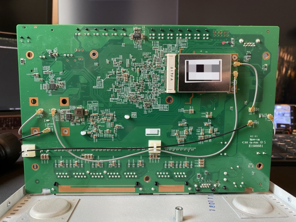
実際に基盤を見てみると、Wi-Fiカードから出ているアンテナケーブルが基盤に入っているため、何かしらの減衰などがされているとのこと。

この減衰をなくすために、アンテナケーブルをWi-Fiカードからアンテナへ直接接続しました。
既存のアンテナケーブルは全て抜線、表側のWi-Fiカードは既存のアンテナケーブルで接続できますが、裏のWi-Fiカードはアンテナケーブルが短かず届かないため、15cmのアンテナケーブルを新規で調達し付け替えました。

こうすることで、確かにどちらも2.4gGhz帯/5Ghz帯共に同じくらいの感度になりました。
エピローグ
以下がChatGPTにまとめてもらったビルド手順です。
正直DTSファイルとかはテキストエディタで修正したので、上手く動く保証はありませんが参考まで。
#!/usr/bin/env bash
# ========= 50E-2R カスタム OpenWrt ビルド一括スクリプト =========

# 0) ソース取得と初期セット
git clone https://git.openwrt.org/openwrt/openwrt.git
cd openwrt
git checkout v24.10.1
./scripts/feeds update -a
./scripts/feeds install -a
wget https://downloads.openwrt.org/releases/24.10.1/targets/mvebu/cortexa9/config.buildinfo -O .config

# 1) menuconfig でプロフィール選択(対話)
make menuconfig   # Target Profile → Fortinet FortiGate 52E-2R → Save/Exit

# 2) 50E-2R 用 DTS を取得
wget https://pastebin.com/raw/fGRaMBuS \
   -O target/linux/mvebu/files-6.6/arch/arm/boot/dts/marvell/armada-385-fortinet-fwf-50e-2r.dts

# 3) DTS 編集:機種名置換+PCIe 3 ポート有効化(これは未検証なので、上手くいくかは知らんです)
FILE=target/linux/mvebu/files-6.6/arch/arm/boot/dts/marvell/armada-385-fortinet-fwf-50e-2r.dts
sed -i \
  -e 's/"Fortinet FortiGate 50E"/"Fortinet FortiWiFi 50E-2R"/' \
  -e 's/"fortinet,fg-50e"/"fortinet,fwf-50e-2r"/' \
  "${FILE}"
printf '\n&pciec { status = "okay"; };\n&pcie1 { status = "okay"; };\n&pcie2 { status = "okay"; };\n' >> "${FILE}"

# 4) rootfs+overlay を論理結合
echo "CONFIG_MTD_VIRT_CONCAT=y" >> target/linux/mvebu/cortexa9/config-6.6

# 5) ビルドをバックグラウンド実行し、ログをリアルタイム表示(ssh切れると困るので、nohupでビルドさせてました)
nohup make -j"$(nproc)" world V=s > build.log 2>&1 &
tail -f build.log
記事は以上


